64 results (0,14824 seconds)

Brand

Merchant

Price (EUR)

Reset filter

Products
From
Shops

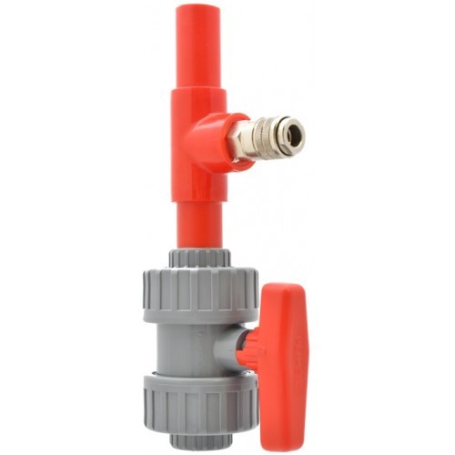
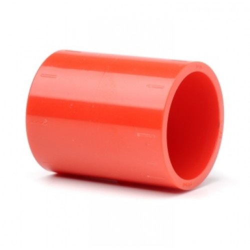
Vesda Xtralis 25mm 2-Way Ball Valve

Vesda VHX-1410 Metal Box HLI Modbus Type 2

Vesda 020-052 19quot Enclosure for Sub-Rack 2 Rows

GBP 2037.12
1

Vesda Xtralis F-PC-2 Standard-Clip for ASD Pipework 2.0mm

Vesda Xtralis F-PC-2 Standard-Clip for ASD Pipework 2.0mm

Vesda Xtralis F-PC-2 Standard-Clip for ASD Pipework 2.0mmA standard clip in red for aspirating holes 2.0mm.When installing an Aspirating Smoke Detection ASD system it is often almost impossible to identify the exact location of sampling point and more importantly identify if the sampling hole is the correct size creating unnecessary delays.The VESDA Standard Clip delivers reliable and accurate sampling hole sizes that are fast to install and easy to locate and identify. Each clip is colour-coded to indicate a specific hole diameter providing an instant visual guide and removing the need for closer inspection.This is particularly beneficial during commissioning and maintenance processes in applications like warehouses or large open spaces. The greatly simplified installation process helps deliver greater reliability in the correct setting of sampling hole size and a faster installation process. A 10mm 2764 diameter drill bit is all that is required by an installer to create each sampling hole rather than many different drill sizes to which the Sampling Hole Clip attaches to.This can help deliver quality installation in projects where installation is sub contracted or the installer is not familiar with the impact of sampling hole size. Use of a chamfered hole entry in the sampling hole clip design can help to reduce dust loading effects.Without using this type of technology a build-up of dust around a standard drilled sampling hole is likely to occur due to the friction created by the airflow through the sampling hole. By reducing dust loading effects and leveraging the additional protection provided by the pipe clips sites can help increase system uptime and potentially extend service and testing intervals.Unlike most contemporary solutions the pipe clip is installation-ready with no need for assembly any additional parts or tools clips are provided as a single ready-to-fit piece.The pipe clips are also available in two formats Standard and Harsh Environment. Harsh Environment Clip variants feature a flexi-lip design that changes its shape when subjected to compressed air.This helps any ice fibre or dust build-up on the supporting rubber structure be easily detached and broken up by the air Jetstream out of the clip hole providing additional protection in challenging locations like freezer applications.Key FeaturesPre-engineered sampling holes for faster more efficient commissioning and installationInstallation-ready design with no part assembly or tools required simply clicks into place for a firm non-slip positionVisual colour-coded guide to sampling point location and sampling hole sizeGreatly simplifies sampling hole drilling a single 10mm drill bit for all holes simply fit the relevant clip to set the hole sizeReduces dust loading effects through inclusion of a chamfered hole entry design helping to increase uptime and potentially extends test intervalsTwo formats available Standard and Harsh EnvironmentHarsh Environment Clip variants feature a flexi-lip design to help reduce sampling hole contamination under high air pressure

GBP 21.32
1

Vesda Xtralis F-PC-HE-2 Freezer Clip for ASD Pipework 2.0mm

Vesda Xtralis F-PC-HE-2 Freezer Clip for ASD Pipework 2.0mm

Vesda Xtralis F-PC-HE-2 Freezer Clip for ASD Pipework 2.0mmWhen installing an Aspirating Smoke Detection ASD system it is often almost impossible to identify the exact location of sampling point and more importantly identify if the sampling hole is the correct size creating unnecessary delays.The VESDA Sampling Hole Clip delivers reliable and accurate sampling hole sizes that are fast to install and easy to locate and identify. Each clip is colour-coded to indicate a specific hole diameter providing an instant visual guide and removing the need for closer inspection. This is particularly beneficial during commissioning and maintenance processes in applications like warehouses or large open spaces.The greatly simplified installation process helps deliver greater reliability in the correct setting of sampling hole size and a faster installation process. A 10mm 2764 diameter drill bit is all that is required by an installer to create each sampling hole rather than many different drill sizes to which the Sampling Hole Clip attaches to.This can help deliver quality installation in projects where installation is sub contracted or the installer is not familiar with the impact of sampling hole size. Use of a chamfered hole entry in the sampling hole clip design can help to reduce dust loading effects.Without using this type of technology a build-up of dust around a standard drilled sampling hole is likely to occur due to the friction created by the airflow through the sampling hole. By reducing dust loading effects and leveraging the additional protection provided by the pipe clips sites can help increase system uptime and potentially extend service and testing intervals.Unlike most contemporary solutions the pipe clip is installation-ready with no need for assembly any additional parts or tools clips are provided as a single ready-to-fit piece. The pipe clips are also available in two formats Standard and Harsh Environment.Harsh Environment Clip variants feature a flexi-lip design that changes its shape when subjected to compressed air. This helps any ice fibre or dust build-up on the supporting rubber structure be easily detached and broken up by the air Jetstream out of the clip hole providing additional protection in challenging locations like freezer applications.Key FeaturesPre-engineered sampling holes for faster more efficient commissioning and installation Installation-ready design with no part assembly or tools required simply clicks into place for a firm non-slip positionVisual colour-coded guide to sampling point location and sampling hole sizeGreatly simplifies sampling hole drilling a single 10mm drill bit for all holes simply fit the relevant clip to set the hole sizeReduces dust loading effects through inclusion of a chamfered hole entry design helping to increase uptime and potentially extends test intervalsTwo formats available Standard and Harsh EnvironmentHarsh Environment Clip variants feature a flexi-lip design to help reduce sampling hole contamination under high air pressureMain ColourTab ColourInchMMRedNA5642.0Please note The image is for illustrative purposes only.

GBP 46.27
1

Vesda Xtralis VIC-030 Multi-Functional Control Card amp Monitored Output for VLF-250 amp VLF-50

Vesda Xtralis VIC-030 Multi-Functional Control Card amp Monitored Output for VLF-250 amp VLF-50

Vesda Xtralis VIC-030 Multi-Functional Control Card Monitored Output for VLF-250 VLF-50The VESDA VLF MCC Multi-function Control Card is an interface card for the range of Xtralis VESDA VLF smoke detectors. An MCC expands the range of input and output communications a VLF detector can perform.Why use a VLF MCCInstalling a VLF MCC into a VLF detector provides a cost-effective solution for customers who need enhanced connectivity fault detection and monitoring and annunciation of alarms and faults. The principal benefits includeImproved FACP connectivity The VLF is fitted with two 2 alarm relays in its standard form. With an extra two 2 relays the Multi-function Control Card allows reporting of all four 4 alarm levels on dry relay outputs.Enhanced annunciation An MPO Monitored 24 V Powered Output is available on the VIC-030 version of the card. The MPO provides power to devices such as sirens or strobes and monitors the line integrity.Enhanced control and fault detection With a VLF MCC installed a VLF has two 2 General Purpose Inputs GPIs allowing for example one GPI to report on loss of mains power and the other GPI to be used as a reset input. The VIC-030 version of the card has a self-configuring GPI depending on the jumper selection for MPORelay3.If MPO is selected activation of the GPI will disable the MPO.If Relay3 is selected the GPI will be set to External Fault e.g. for mains power supply monitoring.Key FeaturesProvides two 2 additional relaysProvides an extra General-Purpose Input GPI with line monitoringQuick and simple to installOut-of-the-box operation with minimal configuration required for extra featuresDiagnostic LEDs give visual indication of the cards statusFully compatible with Xtralis VESDA VLF smoke detector

GBP 397.16
1

Vesda Xtralis VIC-020 Multi-Fuctional Control Card VLF for VLF-250 amp VLF-500

Vesda Xtralis VIC-020 Multi-Fuctional Control Card VLF for VLF-250 amp VLF-500

Vesda Xtralis VIC-020 Multi-Functional Control Card VLF for VLF-250 VLF-500The VESDA VLF MCC Multi-function Control Card is an interface card for the range of Xtralis VESDA VLF smoke detectors. An MCC expands the range of input and output communications a VLF detector can perform.Why use a VLF MCCInstalling a VLF MCC into a VLF detector provides a cost-effective solution for customers who need enhanced connectivity fault detection and monitoring and annunciation of alarms and faults. The principal benefits includeImproved FACP connectivityThe VLF is fitted with two 2 alarm relays in its standard form. With an extra two 2 relays the Multi-function Control Card allows reporting of all four 4 alarm levels on dry relay outputs.Enhanced annunciationAn MPO Monitored 24 V Powered Output is available on the VIC-030 version of the card. The MPO provides power to devices such as sirens or strobes and monitors the line integrity.Enhanced control and fault detectionWith a VLF MCC installed a VLF has two 2 General Purpose Inputs GPIs allowing for example one GPI to report on loss of mains power and the other GPI to be used as a reset input. The VIC-030 version of the card has a self-configuring GPI depending on the jumper selection for MPORelay3.If MPO is selected activation of the GPI will disable the MPO.If Relay3 is selected the GPI will be set to External Fault e.g. for mains power supply monitoring.Key FeaturesProvides two 2 additional relaysProvides an extra General-Purpose Input GPI with line monitoringQuick and simple to installOut-of-the-box operation with minimal configuration required for extra featuresDiagnostic LEDs give visual indication of the cards statusFully compatible with Xtralis VESDA VLF smoke detector

GBP 246.11
1

Vesda PIP-038 ASD Quick Release Kit Air Line ABS 34quot

Vesda PIP-038 ASD Quick Release Kit Air Line ABS 34quot

Vesda PIP-038 ASD Quick Release Kit Air Line ABS 34When the aspirating smoke detection system is installed in a dirty or dusty environment the sampling pipes and sampling holes can get obscured over a period of time by the various airborne particles. As a result it is recommend to clean the sampling pipes and holes by blowing low pressure compressed air in the reverse direction through the sampling pipes. The connection of the compressed air to the sampling pipe and the release of excess air at the end of the sampling pipe can be cumbersome.With introduction of the Quick Release Airline Valve 9-30976 the Large Check Valve 9-10978 and Large 2 Way Ball Valve 9-10980 this does not need to be the case anymore. The quick release airline valve is installed close to the detector. During maintenance the detector can be switched-off and the valve closed to prevent any damage to the detector during the clearing process. The low pressure compressed air can now be easily connected to the quick release.At the far end of the sampling pipe the large check valve or large 2 way ball valve can be used. The check value is the easiest to use as it will automatically open to release excess pressure during the cleaning process and does not require any human interaction. In some cases the check valve might not be suitable and then the 2 way ball valve can be used to manually open the far end of the sampling pipe.Key FeaturesEasy connection of airlineRobust ball valve to protect ASDFor use with 9-10978 - check valve

GBP 105.47
1

Vesda VHX-1400 Metal Box HLI Modbus Type 1

Vesda Xtralis VLP Display Module VSP-002

Vesda Xtralis VSP-004 VLS Display Module

Vesda VRT-W00 Remote Mount Display for VLF cw Remote Termination Card amp No Relays

Vesda VRT-V00 Remote Mount Display for VLF cw Remote Termination Card amp 7 Relays

Vesda WHTSOC-10 Jointing Socket PACK OF 10

Vesda Xtralis REDSOC-10 PIP-002 25mm Jointing Socket Pack of 10

Vesda VHX-0410 Modbus HLI for Darwish amp Honeywell Only

Vesda VHX-0410 Modbus HLI for Darwish amp Honeywell Only

Vesda VHX-0410 Modbus HLI for Darwish Honeywell OnlyThe VESDA ModBus High Level Interface HLI links your VESDAnet with PC software monitoring tools Building Management Systems BMSs or Fire Alarm Control Panels FACPs otherwise known as host that support the ModBus protocol. There are two models availableModBus HLI Type 1 VHX-0400 which echoes each character received on the RS232 link back to the host together with reply message.ModBus HLI Type 2 VHX-0410 which has the echoing function disabled.Key FeaturesDirect access and monitoring of your VESDAnet system.Seamless data transfer.Easily configured using Xtralis configuring and monitoring software packages.DescriptionOne ModBus HLI is used to interface to a VESDAnet. Modbus HLI supports up to a maximum of 40 VESDA detectors on a VESDAnet.The Modbus HLI supports VESDAnet detector zone numbers between 1 to 200. The Modbus HLI divides up the address range into to 7 logical networks. For example the first 30 addresses are considered in network 1 addresses between 31 to 60 are in network 2 and so on.Smoke and Alarm LevelsThe Smoke Level is reported relative to the Fire Alarm threshold where the full scale is 20. For example if the Fire Alarm threshold is 0.5 obsm a level of 0.1obsm is reported as 4. In other words the Actual Smoke level Reported smoke value Fire1 Threshold 20.FaultsAll VESDAnet faults are mapped on one or more of the Modbus HLI faults which are listed belowHead FaultHead Fault Battery and MainsHead Fault Scanner2 and Flow FaultVESDAnet faults categorised as network faults are mapped onto all zones whereas zone faults are mapped onto that particular zone.

GBP 1328.53
1

Vesda-E VEA VER-A40-40-STX 40-Relay Local StaX Silver

Vesda Xtralis RTS151KEY OSID Imager Reset Station Flush Mount

Vesda VHX-0400 PC Link Modbus MK1 HLI Type 1

Vesda VRT-400 LaserSCANNER Display With Remote Termination Card 7 Relays

Vesda VRT-400 LaserSCANNER Display With Remote Termination Card 7 Relays

Vesda VRT-400 LaserSCANNER Display With Remote Termination Card 7 RelaysThe VRT-400 is a LaserSCANNER Display Module with Remote Termination Card.Display modules provide real-time indication of the status of a VESDA detector. They have a 20-segment vertical bar graph display a 2 digit numeric display an audible sounder clear alarm and fault indicators. They also have 4 push button keys to control the detector and the mode of the display.The Display Module can be mounted into a detector unit a remote mounting box or a 19in sub rack. Several displays can be configured to display information from a single detector in multiple locations. There are various versions of the display module depending on the type of detector and the relay configuration required. The LaserSCANNER display has a fourth mode for the Numerical Display which shows the First Alarm SectorFAS this being the number of the sector pipe that has detected smoke. For the LaserCOMPACT the Fire 2 LED is omitted. Smoke levels are continuously shown on a bar graph display where each illuminated segment indicates the current level of detected smoke.The top segment of the bar graph indicates the Fire 1 smoke threshold level and each segment below that level represents 120 of the Fire 1 smoke threshold level. To the left of the bar graph are the Fire 1 Action and Alert smoke threshold indicators. At a glance these provide a visual representation of the programmable alarm thresholds showing how close the smoke level is to triggering the next level of alarm.High intensity flashing LEDs provide a clear indication of the fire condition and are accompanied by an audible warning appropriate to the alarm condition. Similarly any fault condition is indicated by a series of LEDs and an audible tone providing a comprehensive range of status information. The audible warning is easily silenced by pressing the Silence button at which point any flashing LEDs are illuminated until the cause of the event is identified rectified and the system reset.Four large tactile push button keys enable users to reset isolate or silence the detector and control the mode of the display module. The buttons can be disabled to prevent operation of its functions. A lamp test routine is initiated by pressing the Mode key for two seconds. A Manual Scan can be initiated on the LaserSCANNER by holding the Silence button for 2 seconds.Key Features7 RelaysProvides Immediate Status Reporting for a Single VESDA Zone.Allows Zone Control of Assigned VESDA Detector.High Intensity Alarm LEDs.Remote Relay Option.20-Segment Vertical Bar Graph Display.Alarm Threshold Indicators.Built-In Sounder for Audible Warning.Comprehensive Fault Reporting.Multi-mode Numeric Display defaults to smoke obscuration.Recessed Mounting Option.

GBP 1120.91
1

Vesda VRT-K00 Remote Mount Display for VLC with Remote Termination Card No Relays

Vesda VRT-K00 Remote Mount Display for VLC with Remote Termination Card No Relays

Vesda VRT-K00 Remote Mount Display for VLC with Remote Termination Card No RelaysThe VRT-K00 is a Remote Display Module designed for use with the LaserCOMPACT range.Display modules provide real-time indication of the status of a VESDA detector. They have a 20-segment vertical bar graph display a 2 digit numeric display an audible sounder clear alarm and fault indicators. They also have 4 push button keys to control the detector and the mode of the display.The Display Module can be mounted into a detector unit a remote mounting box or a 19in sub rack. Several displays can be configured to display information from a single detector in multiple locations. There are various versions of the display module depending on the type of detector and the relay configuration required. The LaserSCANNER display has a fourth mode for the Numerical Display which shows the First Alarm SectorFAS this being the number of the sector pipe that has detected smoke. For the LaserCOMPACT the Fire 2 LED is omitted. Smoke levels are continuously shown on a bar graph display where each illuminated segment indicates the current level of detected smoke.The top segment of the bar graph indicates the Fire 1 smoke threshold level and each segment below that level represents 120 of the Fire 1 smoke threshold level. To the left of the bar graph are the Fire 1 Action and Alert smoke threshold indicators. At a glance these provide a visual representation of the programmable alarm thresholds showing how close the smoke level is to triggering the next level of alarm.High intensity flashing LEDs provide a clear indication of the fire condition and are accompanied by an audible warning appropriate to the alarm condition. Similarly any fault condition is indicated by a series of LEDs and an audible tone providing a comprehensive range of status information. The audible warning is easily silenced by pressing the Silence button at which point any flashing LEDs are illuminated until the cause of the event is identified rectified and the system reset.Four large tactile push button keys enable users to reset isolate or silence the detector and control the mode of the display module. The buttons can be disabled to prevent operation of its functions. A lamp test routine is initiated by pressing the Mode key for two seconds. A Manual Scan can be initiated on the LaserSCANNER by holding the Silence button for 2 seconds.Key FeaturesProvides Immediate Status Reporting for a Single VESDA Zone.Allows Zone Control of Assigned VESDA Detector.High Intensity Alarm LEDs.Remote Relay Option.20-Segment Vertical Bar Graph Display.Alarm Threshold Indicators.Built-In Sounder for Audible Warning.Comprehensive Fault Reporting.Multi-mode Numeric Display defaults to smoke obscuration.Recessed Mounting Option.

GBP 993.19
1

Vesda VRT-J00 Remote Mount Display for VLC with Remote Termination Card 7 relays

Vesda VRT-J00 Remote Mount Display for VLC with Remote Termination Card 7 relays

Vesda VRT-J00 Remote Mount Display for VLC with Remote Termination Card 7 relaysThe VRT-J00 is a Remote Display Module designed for use with the LaserCOMPACT range.Display modules provide real-time indication of the status of a VESDA detector. They have a 20-segment vertical bar graph display a 2 digit numeric display an audible sounder clear alarm and fault indicators. They also have 4 push button keys to control the detector and the mode of the display.The Display Module can be mounted into a detector unit a remote mounting box or a 19in sub rack. Several displays can be configured to display information from a single detector in multiple locations. There are various versions of the display module depending on the type of detector and the relay configuration required. The LaserSCANNER display has a fourth mode for the Numerical Display which shows the First Alarm SectorFAS this being the number of the sector pipe that has detected smoke. For the LaserCOMPACT the Fire 2 LED is omitted. Smoke levels are continuously shown on a bar graph display where each illuminated segment indicates the current level of detected smoke.The top segment of the bar graph indicates the Fire 1 smoke threshold level and each segment below that level represents 120 of the Fire 1 smoke threshold level. To the left of the bar graph are the Fire 1 Action and Alert smoke threshold indicators. At a glance these provide a visual representation of the programmable alarm thresholds showing how close the smoke level is to triggering the next level of alarm.High intensity flashing LEDs provide a clear indication of the fire condition and are accompanied by an audible warning appropriate to the alarm condition. Similarly any fault condition is indicated by a series of LEDs and an audible tone providing a comprehensive range of status information. The audible warning is easily silenced by pressing the Silence button at which point any flashing LEDs are illuminated until the cause of the event is identified rectified and the system reset.Four large tactile push button keys enable users to reset isolate or silence the detector and control the mode of the display module. The buttons can be disabled to prevent operation of its functions. A lamp test routine is initiated by pressing the Mode key for two seconds. A Manual Scan can be initiated on the LaserSCANNER by holding the Silence button for 2 seconds.Key FeaturesProvides Immediate Status Reporting for a Single VESDA Zone.Allows Zone Control of Assigned VESDA Detector.High Intensity Alarm LEDs.Remote Relay Option.20-Segment Vertical Bar Graph Display.Alarm Threshold Indicators.Built-In Sounder for Audible Warning.Comprehensive Fault Reporting.Multi-mode Numeric Display defaults to smoke obscuration.Recessed Mounting Option.

GBP 1167.56
1

Vesda VRT-800 Remote Mount Display for VLS with Remote Termination Card with 12 Relays

Vesda VRT-800 Remote Mount Display for VLS with Remote Termination Card with 12 Relays

Vesda VRT-800 Remote Mount Display for VLS with Remote Termination Card with 12 RelaysThe VRT-800 is a Remote Display Module designed for use with the LaserSCANNER range.Display modules provide real-time indication of the status of a VESDA detector. They have a 20-segment vertical bar graph display a 2 digit numeric display an audible sounder clear alarm and fault indicators. They also have 4 push button keys to control the detector and the mode of the display.The Display Module can be mounted into a detector unit a remote mounting box or a 19in sub rack. Several displays can be configured to display information from a single detector in multiple locations. There are various versions of the display module depending on the type of detector and the relay configuration required. The LaserSCANNER display has a fourth mode for the Numerical Display which shows the First Alarm SectorFAS this being the number of the sector pipe that has detected smoke. For the LaserCOMPACT the Fire 2 LED is omitted. Smoke levels are continuously shown on a bar graph display where each illuminated segment indicates the current level of detected smoke.The top segment of the bar graph indicates the Fire 1 smoke threshold level and each segment below that level represents 120 of the Fire 1 smoke threshold level. To the left of the bar graph are the Fire 1 Action and Alert smoke threshold indicators. At a glance these provide a visual representation of the programmable alarm thresholds showing how close the smoke level is to triggering the next level of alarm.High intensity flashing LEDs provide a clear indication of the fire condition and are accompanied by an audible warning appropriate to the alarm condition. Similarly any fault condition is indicated by a series of LEDs and an audible tone providing a comprehensive range of status information. The audible warning is easily silenced by pressing the Silence button at which point any flashing LEDs are illuminated until the cause of the event is identified rectified and the system reset.Four large tactile push button keys enable users to reset isolate or silence the detector and control the mode of the display module. The buttons can be disabled to prevent operation of its functions. A lamp test routine is initiated by pressing the Mode key for two seconds. A Manual Scan can be initiated on the LaserSCANNER by holding the Silence button for 2 seconds.Key FeaturesProvides Immediate Status Reporting for a Single VESDA Zone.Allows Zone Control of Assigned VESDA Detector.High Intensity Alarm LEDs.Remote Relay Option.20-Segment Vertical Bar Graph Display.Alarm Threshold Indicators.Built-In Sounder for Audible Warning.Comprehensive Fault Reporting.Multi-mode Numeric Display defaults to smoke obscuration.Recessed Mounting Option.

GBP 1158.24
1